
Apr . 01, 2024 17:55 Back to list
six wire spiral hydraulic hose Performance Analysis
Introduction
Six wire spiral hydraulic hose constitutes a critical component in fluid power systems across diverse industrial applications, including construction machinery, agricultural equipment, and manufacturing processes. Distinguished by its robust construction featuring six spirally wound high-tensile steel wires encased within multiple layers of rubber, this hose offers exceptional pressure resistance, flexibility, and durability. Its technical position within the hydraulic system is as the conduit for transferring hydraulic fluid, enabling the transmission of force for actuation and control. Core performance characteristics include rated working pressure, burst pressure, temperature range, and fluid compatibility. The design mitigates issues common with earlier hose technologies, specifically addressing fatigue failure under pulse pressure and abrasion resistance in harsh environments. This guide provides an in-depth examination of its material science, manufacturing process, performance parameters, potential failure modes, and relevant industry standards.
Material Science & Manufacturing
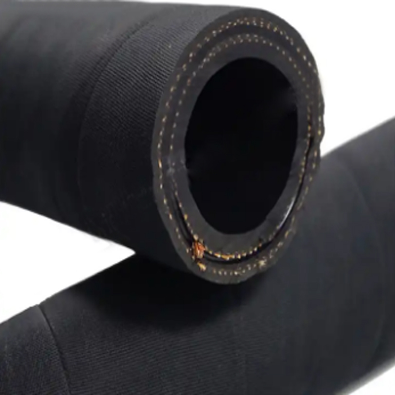
The six wire spiral hydraulic hose is constructed from a complex arrangement of materials, each contributing to its overall performance. The inner tube, typically composed of a synthetic rubber compound such as nitrile (NBR), chloroprene (CR), or ethylene propylene diene monomer (EPDM), provides resistance to the specific hydraulic fluid being conveyed. NBR offers excellent resistance to petroleum-based fluids, CR provides broad fluid compatibility and good weathering resistance, and EPDM excels in high-temperature applications and phosphate ester fluid resistance. The reinforcement layer consists of six high-tensile steel wires, spirally wound for maximum pressure containment. These wires are generally manufactured from high-carbon steel, subjected to surface treatment (e.g., zinc plating) to enhance corrosion resistance. The outer cover, commonly made from a synthetic rubber like CR or polyurethane, provides protection against abrasion, weathering, ozone, and oil exposure. Manufacturing begins with the extrusion of the inner tube. The steel wires are then spirally wound onto the tube using specialized winding machinery, ensuring precise pitch and consistent tension. Multiple rubber layers are subsequently extruded over the wire reinforcement, followed by a final outer cover extrusion. Critical process parameters include temperature control during extrusion, wire tension monitoring during winding, and vulcanization time and temperature for crosslinking the rubber compounds. Proper vulcanization is essential for achieving optimal physical properties, including tensile strength, elongation at break, and hardness. Automated inspection systems are employed to detect defects such as pinholes, voids, and variations in dimensions. Chemical compatibility tests are performed on the inner tube to ensure no degradation occurs from contact with the target hydraulic fluid.
Performance & Engineering
The performance of six wire spiral hydraulic hose is governed by several key engineering principles. The steel wire reinforcement provides the primary resistance to internal pressure, undergoing significant tensile stress under operating conditions. Force analysis dictates the wire diameter and winding pitch necessary to withstand the specified working and burst pressures. The hose’s flexibility is crucial for accommodating bends and movements within the hydraulic system. This flexibility is governed by the hose’s bend radius, which is the minimum radius to which the hose can be bent without kinking or experiencing excessive stress. Environmental resistance is a critical factor. Prolonged exposure to high temperatures can cause rubber degradation, leading to reduced flexibility and increased susceptibility to failure. Ozone exposure can induce cracking in the outer cover. The hose must also exhibit resistance to chemical attack from hydraulic fluids, lubricants, and environmental contaminants. Compliance requirements are substantial. SAE J517, for example, defines the performance standards for hydraulic hose, including pressure ratings, temperature ranges, and testing procedures. The hose's construction must also meet safety regulations related to fluid containment and prevention of leaks. Fatigue analysis is paramount, particularly in applications involving pulse pressure. Cyclic loading can lead to fatigue cracking in the steel wires, ultimately resulting in hose failure. Finite Element Analysis (FEA) is commonly employed to predict the hose’s behavior under various loading conditions and optimize its design for long-term durability. Understanding the fluid's viscosity, temperature, and chemical composition is essential for selecting the appropriate inner tube material to ensure compatibility and prevent swelling or degradation.
Technical Specifications
| Parameter | Unit | Specification Range (Typical) | Testing Standard |
|---|---|---|---|
| Working Pressure | MPa | 20 – 35 | SAE J517 |
| Burst Pressure | MPa | 60 – 105 | SAE J517 |
| Temperature Range | °C | -40 to +100 | SAE J517 |
| Inner Tube Material | - | NBR, CR, EPDM | ASTM D2000 |
| Reinforcement | - | Six High-Tensile Steel Wires | ASTM A938 |
| Outer Cover Material | - | CR, Polyurethane | ASTM D2000 |
Failure Mode & Maintenance
Six wire spiral hydraulic hose is susceptible to several failure modes. Fatigue cracking, often initiated at the intersection of the steel wires and the rubber matrix, is a common cause of failure, particularly in applications with cyclic pressure loading. Abrasion damage to the outer cover can expose the reinforcement wires to corrosion, leading to strength reduction and eventual failure. Internal degradation of the inner tube, caused by incompatible fluids or excessive temperatures, can result in swelling, cracking, and leaks. Kinking or excessive bending can damage the reinforcement wires and compromise the hose’s structural integrity. External damage, such as cuts or punctures, can also lead to immediate failure. Failure analysis typically involves visual inspection, microscopic examination of the fractured surfaces, and chemical analysis of the rubber compounds. Maintenance procedures include regular visual inspections for signs of abrasion, cracking, or leaks. Hose assemblies should be properly supported to prevent excessive bending and strain. The hydraulic fluid should be regularly monitored for contamination and maintained within the recommended viscosity range. Hoses should be replaced at recommended intervals, even if no visible defects are present, to prevent catastrophic failure. Proper hose routing and protection from abrasion are essential preventative measures. Storage of hoses should be in a cool, dry, and dark environment to minimize degradation.
Industry FAQ
Q: What is the impact of pulse pressure on the lifespan of a six wire spiral hose?
A: Pulse pressure, characterized by rapid fluctuations in pressure, significantly reduces the lifespan of the hose. Each pressure pulse induces fatigue stress in the steel wires and the rubber matrix. The magnitude and frequency of these pulses determine the rate of fatigue crack initiation and propagation. Utilizing hoses specifically rated for pulse pressure applications, employing pulsation dampeners in the system, and minimizing pressure spikes through proper system design are crucial mitigation strategies.
Q: How does the selection of inner tube material affect chemical compatibility and hose longevity?
A: The inner tube material must be chemically compatible with the hydraulic fluid being used. Incompatibility can lead to swelling, softening, or degradation of the rubber, resulting in leaks and premature failure. NBR is generally suitable for petroleum-based fluids, while EPDM is preferred for phosphate ester fluids. Careful consideration of the fluid's composition and operating temperature is essential for selecting the appropriate inner tube material.
Q: What are the key considerations for determining the appropriate bend radius for a hydraulic hose?
A: The bend radius is critical to prevent kinking and stress concentration. A smaller bend radius increases the stress on the reinforcement wires, potentially leading to fatigue failure. The manufacturer's specifications should be consulted to determine the minimum allowable bend radius. Factors such as hose size, wire pitch, and operating pressure influence the bend radius requirement.
Q: What are the best practices for inspecting a hydraulic hose for potential failures?
A: Regular visual inspections should focus on identifying cracks, abrasions, bulges, leaks, and any signs of deterioration in the rubber compounds. Pay close attention to the hose ends, where failures often initiate. Conduct a thorough examination of the entire hose length, checking for signs of damage or wear. Additionally, examine the hose for proper installation and support.
Q: How do environmental factors, such as temperature and ozone exposure, impact hose performance?
A: Extreme temperatures can degrade the rubber compounds, reducing their flexibility and increasing their susceptibility to cracking. High temperatures accelerate the aging process, while low temperatures can cause the rubber to become brittle. Ozone exposure can cause cracking in the outer cover, particularly in unsaturated rubber compounds like CR. Utilizing hoses with ozone-resistant outer covers and protecting the hose from direct sunlight can mitigate these effects.
Conclusion
Six wire spiral hydraulic hose represents a robust and reliable solution for demanding fluid power applications. Its design, incorporating high-tensile steel wire reinforcement and carefully selected rubber compounds, provides exceptional pressure resistance, flexibility, and durability. A thorough understanding of the material science, manufacturing processes, and performance parameters is crucial for ensuring optimal operation and preventing premature failure. By adhering to proper maintenance procedures and selecting hoses appropriate for the specific application requirements, users can maximize the service life and minimize the risk of costly downtime.
The long-term performance of these hoses relies heavily on adhering to established industry standards and conducting regular inspections. The application of Finite Element Analysis during the design phase, coupled with rigorous testing to standards like SAE J517, guarantees reliable performance under extreme conditions. Future development will likely focus on enhancing abrasion resistance, improving chemical compatibility with evolving hydraulic fluids, and incorporating smart sensing technologies for real-time condition monitoring.

