
Apr . 01, 2024 17:55 Back to list
Crimping Machine Performance Analysis
Introduction
Crimping machines are integral to the secure assembly of hoses with fittings, prevalent across diverse industries including automotive, hydraulic systems, oil & gas, and construction. These machines utilize controlled compressive force to permanently attach a fitting to a hose, creating a leak-proof seal essential for fluid and gas conveyance. Their technical position in the industrial chain lies between hose extrusion/manufacturing and final system integration. Core performance characteristics revolve around crimp diameter accuracy, crimp force consistency, cycle time, and the ability to accommodate varying hose and fitting materials. The industry currently faces challenges regarding achieving consistent crimp quality across varied production volumes, minimizing fitting deformation during the process, and maintaining adherence to stringent safety standards, particularly in high-pressure applications. This guide provides an in-depth technical overview of crimping machine technology, encompassing material science, manufacturing processes, performance parameters, failure modes, and industry standards.
Material Science & Manufacturing
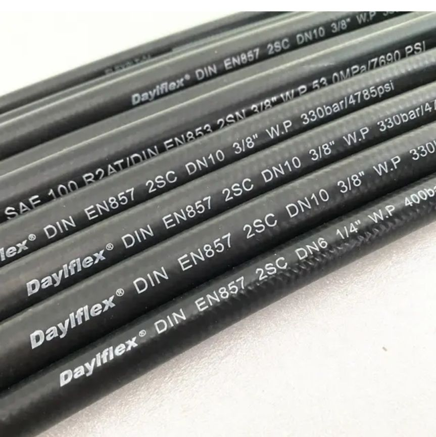
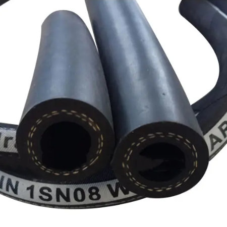
The effectiveness of a crimp connection is heavily reliant on the material properties of the hose, fitting, and the tooling used within the crimping machine. Hoses are commonly constructed from synthetic rubbers (e.g., EPDM, nitrile, neoprene), thermoplastic elastomers (TPEs), or reinforced polymers, each possessing differing tensile strength, elongation at break, and resistance to chemical degradation. Fittings are typically manufactured from carbon steel, stainless steel, brass, or aluminum alloys, impacting corrosion resistance and mechanical strength. The tooling – comprised of dies and segments – are typically manufactured from alloy steels (e.g., 4140, S7) hardened and tempered to achieve high wear resistance and dimensional stability. The manufacturing process of a crimping machine centers around precision machining of the frame, die components, and hydraulic system. Hydraulic systems, using mineral oil or synthetic fluids, deliver the controlled force. Key parameter control involves precise die geometry based on hose and fitting specifications, maintaining consistent hydraulic pressure, and ensuring accurate die alignment. The die design must account for the plastic deformation of the hose material, creating a sufficient interference fit without damaging the fitting or causing hose cracking. Heat treatment of the dies is critical to prevent dimensional changes during operation. Quality control throughout manufacturing includes dimensional inspection of components, hydraulic system pressure testing, and cycle time verification.
Performance & Engineering
Crimping machine performance is fundamentally governed by force analysis, environmental resistance considerations, and compliance with industry-specific standards. Force analysis determines the required crimp force to achieve a predetermined level of interference fit. This calculation considers the hose and fitting dimensions, material properties (yield strength, elastic modulus), and desired crimp percentage. Environmental resistance is crucial, especially in applications exposed to harsh conditions. Corrosion protection of machine components (coatings, lubricants) and selection of compatible hose/fitting materials are paramount. For example, in marine environments, stainless steel fittings and hoses resistant to saltwater degradation are essential. Compliance requirements vary by industry. Automotive applications adhere to SAE standards (e.g., SAE J2044 for power steering hoses), while hydraulic systems often require compliance with ISO standards (e.g., ISO 3766 for hose assemblies). Functional implementation involves precise control of the crimping cycle – approach speed, crimp pressure maintenance time, and retraction speed – to ensure consistent results. Automated crimping machines incorporate programmable logic controllers (PLCs) and feedback sensors (pressure transducers, position encoders) to monitor and adjust these parameters in real-time. Fatigue analysis is vital; repeated crimping cycles can lead to tool wear and machine component fatigue, necessitating preventative maintenance.
Technical Specifications
| Parameter | Typical Value (Hydraulic Crimper) | Unit | Tolerance |
|---|---|---|---|
| Crimping Force | 200 | kN | ±5% |
| Hose Outer Diameter Range | 6 – 51 | mm | ±0.5 mm |
| Fitting Inner Diameter Range | 4 – 42 | mm | ±0.2 mm |
| Crimping Cycle Time | 5 – 15 | seconds | ±1 second |
| Die Set Change Time | 10 – 30 | minutes | N/A |
| Hydraulic System Pressure | 32 | MPa | ±1 MPa |
Failure Mode & Maintenance
Crimping machine failures typically manifest as inconsistent crimp quality, machine downtime, or safety hazards. Common failure modes include die wear and cracking (due to fatigue or impact), hydraulic system leaks (seal failures, hose ruptures), electrical component failures (sensor malfunctions, PLC errors), and mechanical component failures (bearing wear, frame distortion). Fatigue cracking in dies is a critical concern, potentially leading to dimensional inaccuracies and compromised crimp strength. Delamination of hose material can occur if the crimp force is insufficient or unevenly distributed. Degradation of hydraulic fluid can lead to corrosion and reduced system efficiency. Oxidation of metal components can occur in corrosive environments, weakening structural integrity. Regular maintenance is essential. This includes daily inspection of hydraulic hoses and connections for leaks, monthly die inspection for wear and cracks (using dye penetrant testing or ultrasonic inspection), annual hydraulic fluid analysis and filter replacement, and periodic lubrication of moving parts. Preventative maintenance schedules should be based on machine operating hours and production volume. A robust lockout/tagout procedure must be implemented during maintenance to prevent accidental machine activation. Die sets should be periodically re-hardened to restore their original hardness and wear resistance.
Industry FAQ
Q: What are the key differences between radial and axial crimping, and which is generally preferred for high-pressure applications?
A: Radial crimping applies compressive force around the entire circumference of the fitting, while axial crimping applies force along the axis of the fitting. Radial crimping generally provides a more uniform and secure seal, particularly for high-pressure applications, as it maximizes the contact area between the hose and fitting. Axial crimping is typically used for specific fitting designs or lower-pressure applications.
Q: How does hose material affect the optimal crimp force and die selection?
A: Different hose materials have varying degrees of elasticity and yield strength. Softer materials require lower crimp forces to avoid damage, while stiffer materials necessitate higher forces to achieve sufficient interference. Die selection is critical; the die geometry must be precisely matched to the hose and fitting dimensions and material properties to ensure a proper crimp.
Q: What role does die maintenance play in ensuring consistent crimp quality?
A: Die maintenance is paramount. Worn or damaged dies will produce inconsistent crimps, leading to leaks or failures. Regular inspection, cleaning, and re-hardening of dies are essential. Die sets should be periodically replaced when wear exceeds acceptable limits. Maintaining accurate die dimensions is crucial for achieving consistent results.
Q: How can you verify the quality of a crimped connection without destructive testing?
A: Non-destructive testing methods include visual inspection for proper crimp profile and gap closure, leak testing under pressure, and ultrasonic testing to measure crimp interference. However, destructive testing (burst testing) remains the gold standard for verifying crimp strength and reliability. Dimensional measurement of the crimped assembly can also provide valuable insights.
Q: What are the safety considerations when operating a crimping machine?
A: Safety considerations include wearing appropriate personal protective equipment (PPE), implementing a robust lockout/tagout procedure during maintenance, ensuring proper machine guarding, and providing comprehensive operator training. Hydraulic system leaks should be addressed immediately. Emergency stop buttons should be readily accessible and regularly tested.
Conclusion
Crimping machines represent a critical component in numerous industrial applications, requiring precise engineering and adherence to stringent quality control standards. The successful operation of these machines hinges on a thorough understanding of material science principles, accurate force analysis, and consistent maintenance practices. Achieving optimal crimp quality necessitates careful selection of hose and fitting materials, appropriate die design, and rigorous monitoring of process parameters.
Future advancements in crimping technology are likely to focus on automation, enhanced sensor integration for real-time process control, and the development of more robust and durable die materials. Furthermore, integration with Industry 4.0 initiatives, including predictive maintenance algorithms and remote diagnostics, will contribute to improved efficiency and reduced downtime. Ultimately, a commitment to technical excellence and a proactive approach to maintenance are crucial for ensuring the long-term reliability and safety of crimping operations.

